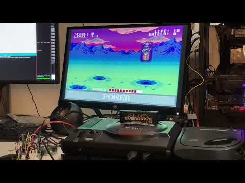
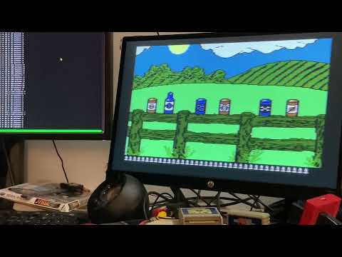
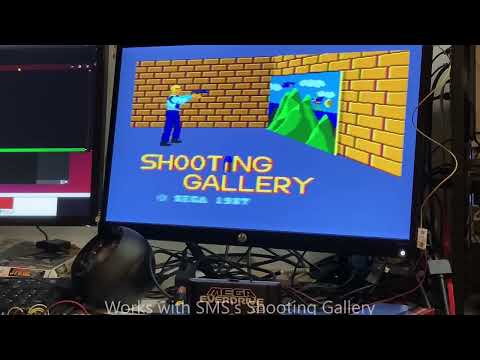
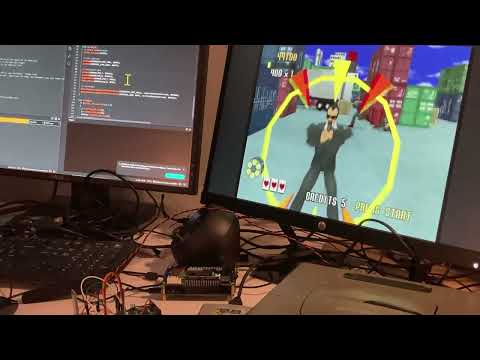
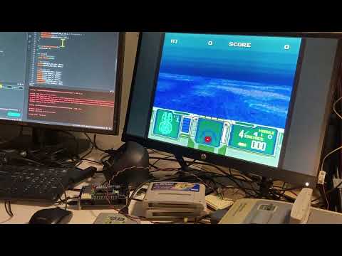
This project started as an attempt to create a flat-screen light-gun to work with a Sega Menacer game I've been (slowly) writing. I've since expanded it to work with other console and games.
This is still pretty early in develppment. I'm not currently happy with the latency and I think I can simplify the hardware side by moving to a different microcontroller. I expect many changes to occur before I make an official release.
IMPORTANT: The circuits in this project are experimental. I am not a practicing electrical engineer. The circuit diagrams here are what I've tested on my video game consoles. The circuits work for me, but I'm not an expert at hardware design. It's possible that I'm doing something incorrectly that may damage a console. USE THIS PROJECT AT YOUR OWN RISK
Most of the code I write are MIT licensed. The Arduino files are LGPL.
Circuit diagrams are "CERN Open Hardware Licence Version 2 - Permissive"
I decided to try making a light-gun about 5 years ago because I had been working with ArUco markers for my Day Job. My original idea was to create a PC based light-gun for use with my own software and emulators. I was going to use ArUco markers to define the bounds of the display.
TODO: add info about
- ArUco Markers
- line along the edge of the display
- QR Code.
TODO: describe IR detection steps
The LM1881 Sync Separator is used to
detect the composite and vertical sync signals from a Sega Genesis. I'm using the
Typical Connection Diagram documented on the first page of the datasheet. Pins 1 and
3 are read by an Arduino Leonardo to simulate timing of a CRT scan
<coming soon~ish>
Setting the Menacer position means pulling the Genesis TH pin low at the appropriate time. I can use the output from a LM1881 sync separator to determine the current scan-line (Y) and wait (X) to set the horizontal position on the scan-line. A few experiments with a Genesis Model 2 and Arduino Leonardo gave me the following values:
- On-screen Y ranges from 30 to 250
- On-screen X ranges from 19 to 68 with delayMicrosecond().
With 68 - 19 = 49 steps, waiting X microseconds to set the horizontal position seems insufficient. I will try a faster microcontroller eventually, but right now I'm using 16MHz Arduino Leonardos.
Sub-microsecond delay increments can be obtained with a custom delay function:
void delayX4Cycles(unsigned int c)
{
        if (--c == 0)
                return;

        // busy wait
        __asm__ __volatile__ (
                "1: sbiw %0,1" "\n\t" // 2 cycles
                "brne 1b" : "=w" (c) : "0" (c) // 2 cycles
        );
}
This gave me an on-screen X range of about 73 to 269 or 196 steps. Which is probably OK considering the resolution of the games.